Capturing network traffic can be a very effective way of solving complicate issues particularly when log files are not yielding useful results. One issue typically is the ability to actually physically perform the capture. Typically you do not have physical access to all devices to setup a local SPAN instance. In other cases a local SPAN is not possible because all ports are presently occupied. A wiring closet may not lend its self well to this type of activity either.
To overcome these limitations a Remote or RSPAN can be used. Essentially this is a SPAN session that writes the output to a specially configured dedicated VLAN. The VLAN spans multiple switches and can be used to deliver traffic to a system with a network analyzer that’s attached to some other switch in another part of the network.
I will jump into the actual configuration here in a second but I must make some cautions before doing so. First, be sure you have the link capacity to handle whatever it is you’re looking to capture. The capture data traverses the same trunks as everything else so know what will happen. Also, be sure to prune this RSPAN VLAN to only the links it must use. RSPAN traffic is flooded to all ports within the VLAN. Finally, be sure you know the utilization of your equipment prior to implementing this. If the CPU of your switches runs high already enabling RSPAN could be more than the device can handle.
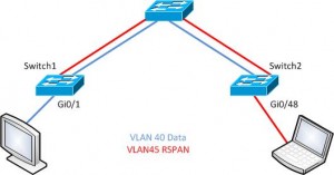
Ok, let’s check out some configuration with the example topology below. The plan is to capture traffic from Switch1 on port Gi0/1. The traffic will ride the RSPAN VLAN to interface Gi0/48 on Switch2. Our typical data VLAN is VLAN 40 and the RSPAN VLAN is ID 45.
First, create the RSPAN VLAN:
Switch1(config)#vlan 45
Switch1(config-vlan)#remote-span
Switch1(config-vlan)#name RSPAN
Ok, that’s it. You will need this on each switch unless of course VTP is propagating this throughout the switched domain. Now, let’s capture traffic and kick it into the RSPAN VLAN.
Switch1(config)# monitor session 5 source interface GigabitEthernet 0/1
Switch1(config)# monitor session 5 destination remote vlan 45
With that completed it’s now time to jump to the far switch and write the traffic out to our sniffer.
Switch2(config)#monitor session 5 source remote vlan 45
Switch2(config)# monitor session 5 destination interface GigabitEthernet 0/48
That’s all there really is to it. There are a few different options for actually filtering traffic that’s captured in a span session. I won’t go into that here as I already made some comments about that in an earlier post you can find HERE.
Note: This does not work with switch traffic such as BPDUs, for instance but should capture all host to network traffic needed to solve problems of that sort.
I would love some feedback on this article so feel free to comment below!

