Layer 2 to Layer 3 Metro-E Link Migration
Metro Ethernet has made connecting different sites extremely easy for just about any level of admin. The problem is, however, it has also made for some very sloppy setups. It is nearly always a recommended best practice to route WAN links. This is particularly true when the WAN is a bottle neck in terms of throughput. If a LAN is built on Gigabit Ethernet and a Metro-E link between sites is only 40Mbps there is a bottleneck. Often LANs in small to medium sized organizations are way underutilized and this can be gotten away with. Typically the Layer 2 connection would span the 40Mbps link with little trouble. However, as traffic increases, a redundant link is added between sites, or requirements change you can find this design corners you with a need for a better way of controlling traffic flow.
The Basics
I took a quick spin around the internet and found a lot on new implementations but was unable to find any great discussions on actually migrating (with minimal user irruption of course) from an L2 to L3 design. If you are reading this feel free to disagree with how I did this by commenting but it worked for me as I worked around my requirements. To get started, the diagram below is what I started with:
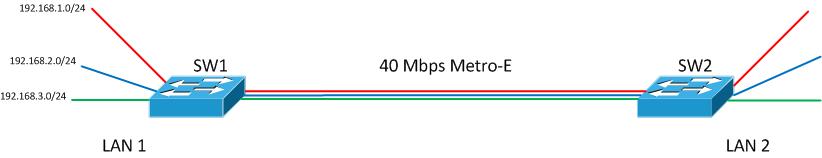
I don’t have the VLANs labeled in the diagram so let’s say Red is management in VLAN 100, blue is voice in VLAN 101 and green is data in VLAN 102. Like I indicated earlier each VLAN spans the WAN link. Also, SW1 is currently the default gateway for each VLAN. The internet router/firewall is not pictured but we would assume it is connected to SW1 as well.
My general project plan in this migration is given immediately below. I will then explain each step in greater detail.
- Enable routing on the remote switch.
- Create a VLAN that exists only on the WAN link for routed traffic.
- Bring up a routing protocol on each switch limiting updates to the WAN VLAN.
- Add new VLANs on the remote switch for hosts. Add subnets to these VLANs.
- Ensure new subnet routes are distributed over entire network. Configure DHCP and other services for these VLANs. Move hosts to new VLANs.
- Verify connectivity and that all hosts at Site 2 are moved to the new VLANs.
- Remove original VLANs from WAN link to keep broadcasts off the WAN.
Enable Routing
First, let’s fully understand the present configuration. SW1 is the default gateway for all the VLANs. There is no routing protocol enabled. It simply forwards any default route traffic to the firewall that I will exclude from the configuration examples to keep them brief and easier to follow. SW1’s routing table looks like this:
SW1# show ip route
…
C 192.168.1.0/24 is directly connected, Vlan100
C 192.168.2.0/24 is directly connected, Vlan101
C 192.168.3.0/24 is directly connected, Vlan102
On SW2 we have only a layer 2 switching configuration currently.
SW2#show ip route
Default gateway is 192.168.1.1

Host Gateway Last Use Total Uses Interface
ICMP redirect cache is empty
As you can see the default gateway is configured but there is no default route. When activating “ip routing” we will need this to be in place for our remote telnet/SSH connection to remain established unless of course we are operating on the same subnet.
SW2#show run | include gateway| route
ip default-gateway 192.168.1.1
! no default route… lets add the route and verify
SW2(config)# ip route 0.0.0.0 0.0.0.0 192.168.1.1
SW2(config)# do show run | include gateway| route
ip default-gateway 192.168.1.1
ip route 0.0.0.0 0.0.0.0 192.168.1.1
OK, I must make a disclaimer here. If you are doing this remotely on your network be sure to know the consequences if connectivity is lost. Perhaps you should employ the router change safety trick I wrote about some time ago.
SW2(config)# ip routing
The change takes a second to happen, at least on the gear I worked with. Your connection may hang or drop for a second but then should reconnect if all else is well. Again, use at your own risk.
Create VLAN for WAN
Now with routing enabled lets add a VLAN over the WAN link to act as our routed link between the two switches. This VLAN is shown as the orange VLAN in the diagram below. Notice also that the L2 VLANs are still in place and will remain in use at this point.
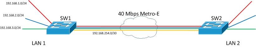
I used VLAN 2 for this with the 192.168.254.0/24 subnet. After creating the VLAN interface on each switch and allowing over it over the trunk I then brought up EIGRP on each of the switches to begin passing routes between the two switches. Before doing that, let’s look at our current routing tables.
SW1# show ip route
…
C 192.168.254.0 is directly connected, Vlan2
C 192.168.1.0/24 is directly connected, Vlan100
C 192.168.2.0/24 is directly connected, Vlan101
C 192.168.3.0/24 is directly connected, Vlan102

SW2# show ip route
…
C 192.168.1.0/24 is directly connected, Vlan100
C 192.168.254.0/24 is directly connected, Vlan2
S* 0.0.0.0/0 [1/0] via 192.168.1.1
Enable Routing Protocol
Now let’s start passing route information on only VLAN 2. Be sure to enable EIGRP with the passive interface set to default to prevent EIGRP data from going out on host facing interfaces.
SW1(config)#router eigrp 100
SW1(config-router)#passive-interface default
SW1(config-router)#no passive-interface vlan 2
SW1(config-router)#network 192.168.0.0 0.0.255.255

SW2(config)#router eigrp 100
SW2(config-router)#passive-interface default
SW2(config-router)#no passive-interface vlan 2
SW2(config-router)#network 192.168.0.0 0.0.255.255
You should then see a new adjacency message after configuration is completed.
%DUAL-5-NBRCHANGE: EIGRP-IPv4:(100) 100: Neighbor 192.168.254.2 (Vlan2) is up: new adjacency
After convergence a quick look at SW2’s routing table to see the new routes.
SW2# show ip route
…
C 192.168.254.0 is directly connected, Vlan2
D 192.168.0.0/24 [90/3072] via 192.168.200.1, 00:00:59, Vlan2
C 192.168.1.0/24 is directly connected, Vlan100
D 192.168.2.0/24 [90/3072] via 192.168.200.1, 00:00:59, Vlan2
D 192.168.3.0/24 [90/3072] via 192.168.200.1, 00:00:59, Vlan2
S* 0.0.0.0/0 [1/0] via 192.168.1.1
Create New Host VLANs
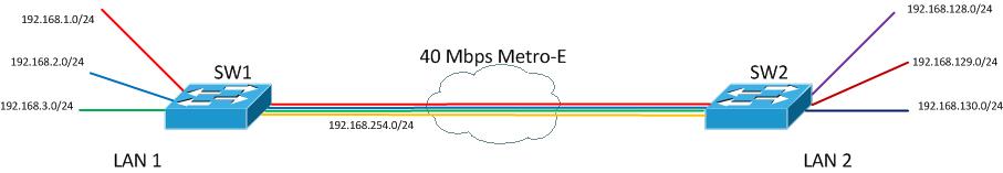
At this point the network still looks like the diagram above. Traffic still flows over the WAN at layer 2. The final step is to implement new VLANs at the remote site that the remote hosts will be moved into. Let’s create the Switched Virtual Interfaces. The IP addresses you assign to the SVI’s will be the new default gateway for host. Create and setup interfaces like this:
SW2(config)#vlan 201
SW2(config-vlan)#vlan 202
SW2(config-vlan)#vlan 203
SW2(config-vlan)#exit
SW2(config)#interface vlan 201
SW2(config-if)#ip address 192.168.128.1 255.255.255.0
SW2(config-if)#interface vlan 202
SW2(config-if)#ip address 192.168.129.1 255.255.255.0
SW2(config-if)#interface vlan 203
SW2(config-if)#ip address 192.168.130.1 255.255.255.0
Migrate and Verify Hosts
With this configuration change made you can now begin testing host connectivity in the new VLANs. I am not going to go into details here. You need to configure applicable DHCP and other network services you may need in the new VLANs. Also, I am not going to detail the process of moving PCs to the new VLANs. The network will be looking something like this:
Cleanup
The final step will be to remove the unused VLANs from the WAN link. Before doing that there are some cleanup and confirmation steps to take. Be warned that ALL hosts at Site 2 must be migrated off of the Site 1 VLANs. In my example, VLAN 100, 101, and 102 would be removed. Any hosts still on VLANs 100, 101, or 102 at Site 2 will lose connectivity when the VLANs are removed from the WAN trunk link.
Another consideration is to update the default route into SW2. If you recall the default route/gateway used to be on VLAN 100 as 192.168.1.1. After removing VLAN 100 form the WAN trunk this route will break. Be sure you will be able to maintain connectivity and update this with a simple default “ip route” command:
SW2(config)# ip route 0.0.0.0 0.0.0.0 192.168.254.1
SW2(config)#no ip route 0.0.0.0 0.0.0.0 192.168.1.1
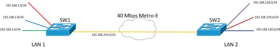
Finally, remove the VLANs from the trunk. Again, in your situation know the ramifications of this.
SW2(config-if)# switchport trunk allowed vlan remove 100,101,102
The resulting topology will look something like this:
I hope some finds this useful. If there are any areas that are unclear or confusing let a comment below and I will try to address them. Also, if you have addresses a similar situation in the past we would love to hear about it!