Cisco Layer 2 Tunneling
To a student of networking the OSI model can be a little hard to appreciate until its application is actually seen a few times in the real world. Likewise understanding that you can grab frames or packets and encapsulate them inside other higher layer protocols is also confusing to the newbie. An Ethernet pseudo-wire is a great example of this. Essentially, you can capture an entire Data Link layer frame as it enters an interface, encapsulate it, and deliver it out another interface no matter what type of network you have in between. Cool stuff right? Let’s dive in and see how it works!
First, we will need to fire up GNS3 and create a topology. I use two routers to tunnel and a router on each end to test connectivity through the tunnel. It’s going to look something like this:
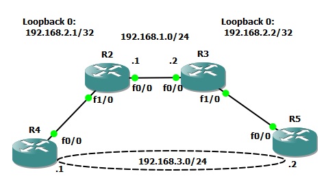
The goal is to get R4 an R5 talking directly at the Layer 2 Ethernet level with one another.
First we need to configure R2 and R3 to talk and share routing information. I’m not going to detail that as you probably would already know how to do that if you’re reading this article. I did establish two loopback interfaces, one on each router. This will be the IP address listening for the connection from the other router in order to establish the pseudo-wire. Again, make sure there is a route to this loopback on the opposing router and we’re set.
Next, create a “pseudowire-class” on each router. You will need to specify the encapsulation and the local interface. Specify the loopback here.
R2:
pseudowire-class R2toR3
 encapsulation l2tpv3
 ip local interface Loopback0
R3:
pseudowire-class R3toR2
 encapsulation l2tpv3
 ip local interface Loopback0
Now it’s time to configure the physical interface. I used the FastEthernet 1/0 interfaces on R2 and R3. Remove all configurations and configure with the “xconnect” command calling the pw-class from the previous step. Xconnect is like cross connect. Think of it as a virtualized physical cross connect you would make with a patch cable. In other words, we are creating a point to point circuit over a packet switched network. You also must specify the remote routers loopback IP address. You can see this all laid out in the configuration below:
R2:
interface FastEthernet1/0
 no ip address
 duplex auto
 speed auto
 no cdp enable
 xconnect 192.168.2.2 100 encapsulation l2tpv3 pw-class R2toR3
R3:
interface FastEthernet1/0
 no ip address
 duplex auto
 speed auto
 no cdp enable
 xconnect 192.168.2.1 100 encapsulation l2tpv3 pw-class R3toR2
Verify the tunnel is up with the “show l2tun” command. If its not be sure the xconnected interfaces are administratively up by issuing the “no shutdown” command. They seemed to shut down as a result of the xconnect command in my experience.
R2:
#show l2tun

%No active L2F tunnels

L2TP Tunnel and Session Information Total tunnels 1 sessions 1

LocID RemID Remote Name   State  Remote Address  Port  Sessions L2TP Class/
                                                                VPDN Group
37239 61815 R3            est    192.168.2.2     0     1        l2tp_default_cl

LocID      RemID      TunID      Username, Intf/      State  Last Chg Uniq ID
                                 Vcid, Circuit
31310      47901      37239      100, Fa1/0           est    01:02:30 4

%No active PPTP tunnels
With the pseudo-wire tunnel up lets now jump to R4 and R5. Configure the FastEthernet 0/0 interfaces as if they are cable directly together. IP address and turn up the interfaces. After a few seconds they should exchange CDP information through the tunnel and appear as neighbors. Remember, CDP is a Layer 2 muilticast and its tunneled in the case of L2.
R5#show cdp neighbors
Capability Codes: R - Router, T - Trans Bridge, B - Source Route Bridge
                  S - Switch, H - Host, I - IGMP, r - Repeater

Device ID        Local Intrfce     Holdtme    Capability  Platform  Port ID
R4.lab.local     Fas 0/0            169         R S       2621      Fas 0/0
Now, go ahead and ping through the tunnel with R5 to R4. Review the MAC address table of R5 and the interface MAC of R4. See? L2 connectivity!
R5#ping 192.168.3.1 repeat 1

Type escape sequence to abort.
Sending 1, 100-byte ICMP Echos to 192.168.3.1, timeout is 2 seconds:
!
Success rate is 100 percent (1/1), round-trip min/avg/max = 60/60/60 ms

R5#show arp
Protocol  Address          Age (min)  Hardware Addr   Type   Interface
Internet  192.168.3.2             -   c806.338c.0000  ARPA   FastEthernet0/0
Internet  192.168.3.1            94   c805.338c.0000  ARPA   FastEthernet0/0
R4#sh int fa 0/0

FastEthernet0/0 is up, line protocol is up
  Hardware is AmdFE, address is c805.338c.0000 (bia c805.338c.0000)
  Internet address is 192.168.3.1/24
  MTU 1500 bytes, BW 100000 Kbit, DLY 100 usec,
....
Now, let’s try something… We will again ping through the tunnel but will this time capture traffic between R2 and R3. Start a capture in GNS3 between R2 and R3 and then issue two ping commands like this on R5:
R5#ping 192.168.3.1 repeat 1 size 100

Type escape sequence to abort.
Sending 1, 100-byte ICMP Echos to 192.168.3.1, timeout is 2 seconds:
!
Success rate is 100 percent (1/1), round-trip min/avg/max = 152/152/152 ms
R5#ping 192.168.3.1 repeat 1 size 1500

Type escape sequence to abort.

Sending 1, 1500-byte ICMP Echos to 192.168.3.1, timeout is 2 seconds:
!
Success rate is 100 percent (1/1), round-trip min/avg/max = 88/88/88 ms
Now, stop the capture. You will notice I sent a 100 and a full 1500 byte packet in the commands above. You can download a copy of my capture HERE if you would like to actually see these pings flow over the wire. I will be speaking to this capture specifically so feel free to open it up and follow along. Look at packets 1 and two and then 3 through 6. You will notice these packets are sourced from the loopback addresses. This is the “tunneled” ICMPs we just sent!
You will notice, however, that the data is not listed as ICMP but rather L2 Tunneling Protocol V3. The ICMP frame / packet is encapsulated in its entirety. The traffic is not encrypted so we can actually look inside of the packet and see information if we care to do so. For instance, in the packet below you will notice I underlined the IP addresses in hexadecimal format that are part of the data section of the packet as opposed to the first header.
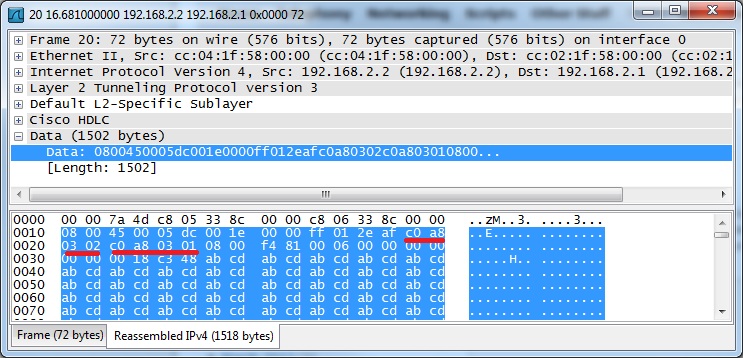
Jumping back to the full capture look again at packets 1 and 2. This was the first ICMP ping that was sent. You will notice the packet was 152 bytes in size. This is the full frame length including all headers of the base packet and the encapsulated packet. Now look at frames 3 through 6. You will notice there are four packets for only a single ICMP exchange. What’s up? If you look back to the second command we issued you will notice we sent a full 1500 bytes. As you may well know this is the fullest packet that can be sent under typical Ethernet circumstances. However, the circumstances are not “normal”. Remember we are tunneling the traffic over our pseudo-wire and that extra header has to go someplace! The additional packets are actually fragmented as a result. You can see Wireshark is indicating this to us anyhow with the “Reassemble” notice at end of the info column.
![]()
Now that we have seen the traffic tunneled let’s have a look at the end points. Issue the same two ping commands again but this time capture at one of the end routers. You can download the capture file HERE if you would like to take a closer look.
As you can quickly see there are only a total of four ICMPs in this capture. Why? The tunneling feature in the router reassembles the packet at the tunnel termination point and forwards it back out as it was received.
I hope this has been an educational experience for anyone who has not worked with L2 tunneling or pseudo-wires in the past. There are many other additional things you could do with this as well. For example try tunneling 802.1Q VLAN tagged traffic! Thanks for reading and feel free to leave your comments, or suggestions!