802.1Q Tunneling AKA QinQ
You are probably familiar with VLAN tagging on switch trunks and how it can be used to separate physical infrastructures into multiple logical networks. With the explosive growth of Metro Ethernet connections the ability of site to site layer two connections has now become common. It’s easy for organizations to implement as network admins are already familiar with Ethernet as a LAN protocol. The setup is simple for the customer but a bit more configuration is needed on the service provider’s side if the customer desires VLAN tagged traffic to flow over the site to site link.
Theory
Before looking at any configuration lets have a look at the frame layout. In an 802.1Q frame you would have something like shown below. 12 bytes of addressing, tag, ethertype and layer three payload.
------------------------------------------------------
| Ethernet | Tag  |  EtherType | Payload...
------------------------------------------------------
     12        4        2           x
To allow the service provider to continue using all 4096 VLAN ID’s without worrying about interference with customer tags the frame is simply expanded to add an additional tag. In the double tagged frame there are “inner” and “outer” tags known more officially as “S” and “C” tags. You can think “S” for service provider and “C” for customer. You will want to know the “S” and “C” terminology as other vendors reference it by that name in their configurations. The frames look something like this:
----------------------------------------------------------------
| Ethernet  |  S-Tag  | C-Tag  |  EtherType | Payload...
----------------------------------------------------------------
     12          4        4           2           x
Implementation
Let’s implement this on some real world gear and see how things work. First, we must configure the MTU on the provider switches. This has to be bumped up to 1504 from the typical 1500 because of the added 4 bytes of the “outter” S-Tag.
SP(config)#system mtu 1504
Changes to the system MTU will not take effect until the next reload is done
Be prepared to reload the switch if needed. The MTU settings can then be verified with “show system mtu”.
Our network will be configured like this:
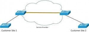
In this design we will configure the interfaces between service provider switches something like this:
SP1(config)# interface gi0/1
SP1(config-if)# switchport trunk encapsulation dot1q
SP1(config-if)# switchport mode trunk
SP1(config-if)# switchport trunk allowed vlan 100
We are dedicating only VLAN 100 to our customer’s traffic allowing all other VLANs for service provider later use. Now, let’s configure the customer facing edge ports.
SP1(config)# interface f0/1
SP1(config-if)# description Customer XYZ
SP1(config-if)# switchport access vlan 100
SP1(config-if)# switchport mode dot1q-tunnel
SP1(config-if)# l2protocol-tunnel
Basically what is happening is “access vlan 100” puts everything coming from the customer into VLAN 100 while “mode dot1q-tunnel” allows tags to be preserved rather than stripped as typically the case with access ports. The service provider will tag native VLAN frames as well but only with the “S-Tag” when traversing the providers switches. Additionally, I enabled “l2protocol-tunnel” which allows CDP, VTP and LLDP to flow over the service provider switches between customer switches as if they were directly connected.
A final consideration is if you will be tagging the customers native VLAN. I would suggest enabling this no matter what. This feature is activated with the global configuration mode command:
SP1(config)#vlan dot1q tag native
To verify the above configuration we can issue the “show dot1q-tunnel commands as shown below:
S1# show dot1q-tunnel

dot1q-tunnel mode LAN Port(s)
-----------------------------
Fa0/1
“show l2protocol-tunnel” will then show us the tunneling statisics of that configuration.
SP1#show l2protocol-tunnel

COS for Encapsulated Packets: 5

Drop Threshold for Encapsulated Packets: 0

Port                Protocol    Shutdown  Drop      Encaps    Decaps    Drop

Threshold Threshold Counter   Counter   Counter

------------------- ----------- --------- --------- --------- --------- ---------

Fa0/1
cdp           ----      ----            3         3         0

lldp          ----      ----            0         0         0

stp           ----      ----            0        84         0

vtp           ----      ----            0         0         0

---           ----      ----         ----      ----      ----

---           ----      ----         ----      ----      ----

---           ----      ----         ----      ----      ----
From a customer device perspective you can also check the CDP neighbor information to see if the other sites switch is shown.
Site2SW#show cdp neighbors

Capability Codes: R - Router, T - Trans Bridge, B - Source Route Bridge

S - Switch, H - Host, I - IGMP, r - Repeater, P - Phone,

D - Remote, C - CVTA, M - Two-port Mac Relay

Device ID        Local Intrfce     Holdtme    Capability  Platform  Port ID

Site1SW             Gig 0/1              131              S I   WS-C2560-           Gi 0/1
I hope this was helpful to anyone trying to better familiarize themselves with the QinQ concept and configuration!