Basic Routing Protocol Configuration in VRF Lite
You may recall me posting a basic conceptual article about VRF’s and VRF lite implementation. Well, I am finally back with some more advanced concepts. What good are separate routing instances without the ability to use routing protocols to share routes between routers? Let’s dive right in and see how it’s done!
Interface Configurations
Lets get started by looking at a simple sample topology. I have this running in GNS3 but could easily be duplicated with physical routers or L3 switches with an IP services image. This topology is as simple as it gets and really would not be practical other than for a demo like this. Since VRFs are a more advanced topic you should already have the knowledge to spin this demo up in your environment. Essentially, I am building a simple two router topology throwing all of the interfaces and routes into a VRF rather than the base routing instance.
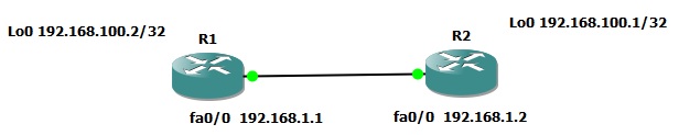
First, establish the VRF. Define a route distinguisher as well. Next, configure some interfaces to be members of the VRF. I used physical interfaces as we are only really testing here. In practicality you will probably be using a logical or sub interface or the configuration will be at least somewhat more difficult to look at; trust me. IP address the interface AFTER it’s added to the VRF and ensure it’s online. I created a loopback as well in the same manner just to give myself a network to kick around with our routing protocols. You can see the begging’s of this below on R1.
ip vrf TEST
rd 100:1

interface Loopback0
ip vrf forwarding TEST
ip address 192.168.100.2 255.255.255.255

interface FastEthernet0/0
ip vrf forwarding TEST
ip address 192.168.1.1 255.255.255.0
Ditto for R2:
ip vrf TEST
rd 100:1

interface Loopback0
ip vrf forwarding TEST
ip address 192.168.100.1 255.255.255.255

interface FastEthernet0/0
ip vrf forwarding TEST
ip address 192.168.1.2 255.255.255.0
EIGRP Configuration
With the interfaces “up and up” it’s time to have a look at the routing protocols. Let’s start with EIGRP. The EIGRP configuration for VRF instances is not difficult but the steps are a little bit different than the basics. First, start out by creating an EIGRP process as normal. Next, define an address-family specifying the VRF name. Next, add the network definitions as per normal. If you want to disable auto summarization now is also the time for that. You must explicitly define the autonomous system number of the VRF and finally you can exit the address family configuration mode. On R1 the configuration fell together like this:
router eigrp 100

address-family ipv4 vrf TEST
network 192.168.0.0 0.0.255.255
no auto-summary
autonomous-system 100
exit
R2 was the same configuration exactly in this simple example.
If everything worked out your “TEST” VRF instances should now be exchanging routing data. Have a look at this with commands like “show ip route vrf TEST” and “show ip eigrp vrf TEST topology”. You can see examples of this below:
R1#show ip route vrf TEST

Routing Table: TEST

.....

192.168.30.0/32 is subnetted, 1 subnets
D 192.168.30.1 [90/156160] via 192.168.1.2, 00:41:18, FastEthernet0/0
C 192.168.1.0/24 is directly connected, FastEthernet0/0
192.168.100.0/32 is subnetted, 2 subnets
D 192.168.100.1 [90/156160] via 192.168.1.2, 00:42:39, FastEthernet0/0
C 192.168.100.2 is directly connected, Loopback0

R1#show ip eigrp vrf TEST topology
IP-EIGRP Topology Table for AS(100)/ID(192.168.100.2) Routing Table: TEST

Codes: P - Passive, A - Active, U - Update, Q - Query, R - Reply,
r - reply Status, s - sia Status

P 192.168.100.1/32, 1 successors, FD is 156160
via 192.168.1.2 (156160/128256), FastEthernet0/0
P 192.168.100.2/32, 1 successors, FD is 128256
via Connected, Loopback0
P 192.168.1.0/24, 1 successors, FD is 28160
via Connected, FastEthernet0/0
P 192.168.30.1/32, 1 successors, FD is 156160
via 192.168.1.2 (156160/128256), FastEthernet0/0
Great! EIGRP is moving routing information around as we would expect. Redistributing a route into a VRF instance is essentially what you would expect as well. Let’s create a null route on R1 and distribute it to R2 just for the sake of experimentation. It would look something link this:
ip route vrf TEST 192.168.255.0 255.255.255.255 Null0

router eigrp 100
address-family ipv4 vrf TEST
redistribute static
Nothing to it! Now, jump over to R2 to verify the route was shared:
R2# show ip route vrf TEST
……
192.168.255.0/32 is subnetted, 1 subnets
D EX 192.168.255.0 [170/28160] via 192.168.1.1, 00:11:09, FastEthernet0/0
C 192.168.1.0/24 is directly connected, FastEthernet0/0
192.168.100.0/32 is subnetted, 2 subnets
C 192.168.100.1 is directly connected, Loopback0
D 192.168.100.2 [90/156160] via 192.168.1.1, 00:30:22, FastEthernet0/0
As you can see the route to “192.168.255.0” is displayed and is listed as EIGRP External since it’s a redistributed route.
OSPF Configuration
With EIGRP in place lets pull back and repeat the configuration but with OSPF this time. We will use the same interface configurations as above.
The OSPF configuration is a bit different than EIGRP and in my opinion a little more intuitive. First, we will create the OSPF process actually specifying the VRF as part of this process. Next, add the networks you would like to include in this process specifying the OSPF area as well. From the bare basic standpoint, that’s it! The configuration is shown below from R1:
router ospf 100 vrf TEST
network 192.168.0.0 0.0.255.255 area 0
After issuing the same commands on R2 and allowing the protocol to update we can see the routing table reflects the changes:
R2#show ip route vrf TEST
Routing Table: TEST
….
C 192.168.1.0/24 is directly connected, FastEthernet0/0
192.168.100.0/32 is subnetted, 2 subnets
C 192.168.100.1 is directly connected, Loopback0
O 192.168.100.2 [110/2] via 192.168.1.1, 00:04:55, FastEthernet0/0
If we again would like to add and distribute the static route from the previous EIGRP example from R1 we can enter the route and appropriate configuration like this:
ip route vrf TEST 192.168.255.0 255.255.255.255 Null0
router ospf 100 vrf TEST
redistribute static subnets
Jumping over to R2 again we can see this reflected in the routing table:
R2#show ip route vrf TEST

Routing Table: TEST
…..
192.168.255.0/32 is subnetted, 1 subnets
O E2 192.168.255.0 [110/20] via 192.168.1.1, 00:00:05, FastEthernet0/0
C 192.168.1.0/24 is directly connected, FastEthernet0/0
192.168.100.0/32 is subnetted, 2 subnets
C 192.168.100.1 is directly connected, Loopback0
O 192.168.100.2 [110/2] via 192.168.1.1, 00:00:10, FastEthernet0/0
Thank you for this tutorial.. I was looking for some info about vrf lite.. this article helped a lot!